Habitat Airlock Linkage System
Optimized four-bar linkage for rapid button actuation
Project Overview
Imagine a mechanical device that needs to press a button as fast as possible—like an airlock mechanism on a space habitat. This project designed and optimized a four-bar linkage (a classic mechanism with four connected bars that converts rotational motion into complex paths) to actuate a button reliably and quickly. The challenge: minimize weight to maximize speed, while keeping the mechanism strong enough not to break.
Design Goals
- Minimize mass — reduce weight for faster actuation
- Reduce stress concentrations — FEA-guided filleting
- Ensure reliability — repeatable, robust operation
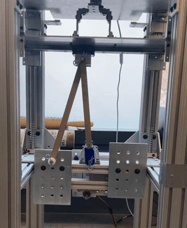
The linkage system during final performance testing.
Performance Results
The target: press the button within 30 seconds. We beat that in both tests, and the final design weighed less than a third of our initial attempt. Here's how the numbers stacked up:
Test Results
- Intermediate test — 27.55 seconds
- Final test — 25.91 seconds
- Mass reduction — 72.4% from initial design
Key improvements included filleting hexagonal hole edges to reduce stress concentrations and optimizing link geometry to reduce mass and inertia.
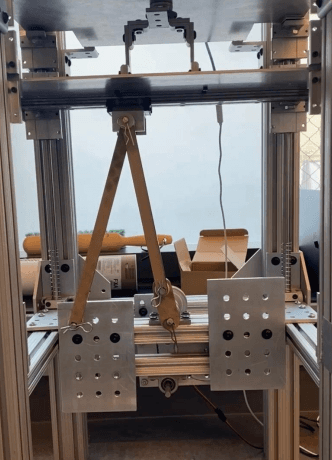
Linkage system during intermediate performance testing.
Initial Design Phase
We didn't just pick one design—we explored six different linkage configurations using an online kinematic simulator. Each had different trade-offs in reach, speed, and mechanical advantage. We narrowed down to three finalists, then combined the best features into our final design.
The selected design predicted ~30 second actuation time based on simulations—right at our target. Good enough to start building and testing.
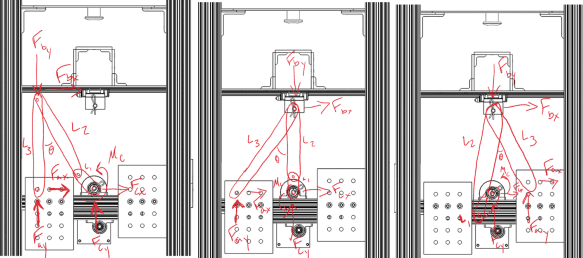
Linkage designs explored using an online kinematic calculator.
Stress Analysis and FEA
Light is fast, but too light means it breaks. We analyzed three critical positions where the linkage experiences maximum stress—when it's most likely to fail. Finite Element Analysis (FEA) simulations showed exactly where stress concentrated: around holes and sharp corners. That's where cracks start, so we added fillets (rounded edges) to spread the load.
Basic stress calculation (Force / Area)
FEA simulations verified manual calculations and identified stress concentrations around holes and sharp corners, informing fillet additions.
Material Selection
- Material — 1/4" thick acrylic
- Link width — 2 inches
- Safety factor — 16× (yield strength / max stress)
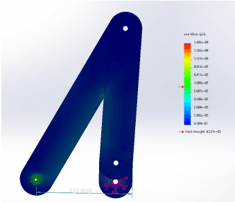
FEA stress distribution on linkage component.
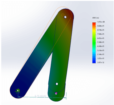
FEA displacement under load.
Fabrication and Assembly
With the design validated in simulation, we laser-cut the acrylic links and assembled the mechanism. First test: 28 seconds—faster than predicted! But we saw opportunities to go even faster.
Identified Improvements
- Reduce link width — decrease mass and inertia
- Add fillets — reduce stress at critical edges
- Optimize clearances — improve assembly precision
Iterative Design Refinements
Engineering is iterative: test, learn, improve, repeat. After the first build, we made targeted changes based on real-world performance and FEA insights. The result? Faster actuation, lower mass, and the same structural safety margin.
Key Learnings
- Iterative methodology — systematic application of test learnings
- FEA-guided design — data-driven stress reduction
- Mass optimization — improved speed without sacrificing strength
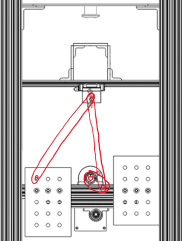
CAD modifications illustrating the iterative design process.